| View previous topic :: View next topic |
| Author |
Message |
Mystic_Merlin
Joined: 15 Oct 2007
Posts: 533
Location: Bangkok
|
 Posted: Wed May 20, 2009 4:45 pm Post subject: Restoring a SPF16...the new challenge! Posted: Wed May 20, 2009 4:45 pm Post subject: Restoring a SPF16...the new challenge! |
 |
|
Here I go again..with a broken copier to restore! 
Only this time I spent so much time on it already, I'll try fixing it avoiding posting questions on the board, hopefully it will be just a WIP...can it be done?
This one is a serious challenge...if you thought the copiers I acquired lately were in bad shape, well check this out:
First I was lucky to spot that weird silver looking device on ANOTHER pile of junk (my favorite play ground  )...actually it was laying next to the SP3200 )...actually it was laying next to the SP3200
I looked at the device not sure about what it was until I saw the cartridge port...a Super Pro Fighter? No way...how could someone spray painted it that way...  . (I'll post the picture if I can fix it) . (I'll post the picture if I can fix it)
Without even opening the device I plugged it on the top of the SFC and switched it on...BOOM! Something exploded inside, the smoke was coming out from the cartridge port, freaky!
First lesson: always open a weird looking copier before you switch it on.
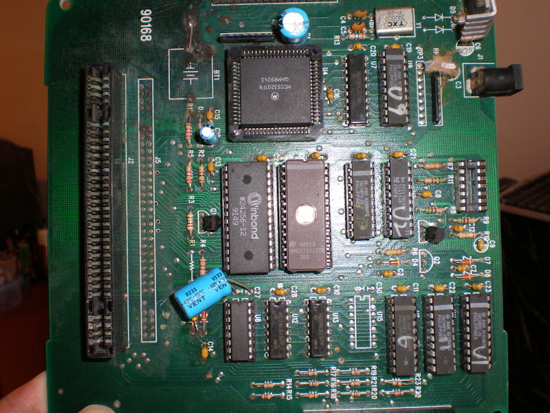
Now let's take a close look:
- busted 7805 regulator
- busted capacitor (the one that exploded because of the broken 7805)
- leaked battery
The first 2 components were easy to replace
Let's switch it on again...nice, I get the screen...but as I feared, floppy drive not working.
First I test the drive on another copier...not dead but quite...
Then I test another drive on the SPF, still absolutely no reaction...mmm
I test the floppy connector: busted!
Damn! I start to realize the leaked battery did some serious damage...time to make some continuity tests:
I notice some traces from the FD connector on the top layer of the PCB are not properly connected to the FD controller. Sh*t! too little space to work on there. Fortunately all these solder joints are going through the PCB to the bottom layer...I start wiring those having continuity test failures:
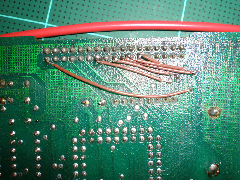
Phewww... that was not an easy job, cutting the wires to the right size and solder them without bridging any connection. that was not an easy job, cutting the wires to the right size and solder them without bridging any connection.
Now let's test...STILL NOTHING from the floppy drive...
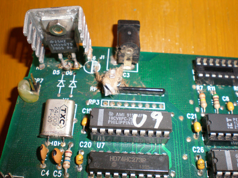
Damn...I scratch my head then remember Kaz who got my SPF clone (http://tototek.com/phpBB2/viewtopic.php?t=2252&highlight=supercom) had similar issues, and confirmed me by email that he ended up changing the PLCC socket of the FDC...
Although I could spot some rust on the side facing the leaked battery, I would never have expected such a disaster when I lifted the FDC from the PLCC socket:
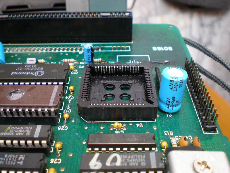
All the pins have some minor cuts. No choice I gotta take off this PLCC socket:
What's left to do:
- solder another PLCC socket
- replace the components next to it: a capacitor, and a resistor network a472j I believe to be a 4.7 kohms
- cross my fingers that I get this machine to work again one day!
So let's sum up the damage of the leaked battery so far:
It spreaded to the cartridge port.
It spreaded to the floppy connectors (I had to sand the pins to make contact)
It spreaded to the floppy drive data cable...on BOTH SIDES!
It speaded to the PLCC and broke its thin pins.
That was definitely not a good designing choice from CCL to place the battery so close to some key components...well definitely not a good choice to place any NiCd battery at all!
|
|
| Back to top |
|
 |
CrackLtd
Joined: 05 Feb 2007
Posts: 239
|
| Posted: Wed May 20, 2009 7:55 pm Post subject: |
|
|
| Please, can you take a photo of that junkyard you find all your copiers? I really would like to see that (: ....
|
|
| Back to top |
|
|
madman
Joined: 07 Jul 2006
Posts: 598
|
| Posted: Wed May 20, 2009 8:53 pm Post subject: |
|
|
You find the absolute worst condition copiers  Are these in cases, or just the bare boards that you post pictures of? Are these in cases, or just the bare boards that you post pictures of?
As for the battery placement...it's typical Chinese mentality. Chinese goods are always about making a quick buck, never about long term longevity. CCL probably knew they'd be long gone by the time any problems w/leakage came about.
|
|
| Back to top |
|
|
Mystic_Merlin
Joined: 15 Oct 2007
Posts: 533
Location: Bangkok
|
|
| Back to top |
|
|
CrackLtd
Joined: 05 Feb 2007
Posts: 239
|
| Posted: Thu May 21, 2009 7:06 am Post subject: |
|
|
| Great, you called that pic 'market', lol. Maybe you have to give that dude sitting there a nickle for every junkitem you pick up there, eh? But seriously, its the mentality of throwing everything away instead of repairing it and continue using it that destroys the earth. Soon any place will look like that place in that picture. So its cool you invest your personal time in repairing stuff and bring it back into the comunity.
|
|
| Back to top |
|
|
Mystic_Merlin
Joined: 15 Oct 2007
Posts: 533
Location: Bangkok
|
| Posted: Thu May 21, 2009 9:55 am Post subject: |
|
|
| CrackLtd wrote: | | Great, you called that pic 'market', lol. Maybe you have to give that dude sitting there a nickle for every junkitem you pick up there, eh? But seriously, its the mentality of throwing everything away instead of repairing it and continue using it that destroys the earth. Soon any place will look like that place in that picture. So its cool you invest your personal time in repairing stuff and bring it back into the comunity. |
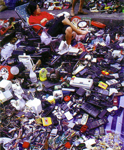
I don't know if it does exist in every country but I understand there's real massive junk industry in Thailand. Some huge junkyards are collecting items and sell them back (per kg?)...I'm not sure we can call that "recycling" but it's better than leaving those items in the nature...garbage selection is the first step to recycling.
As for my interest in repairing there's no other purpose than educating myself on these devices and preserve them from certain death.
I hate to throw away stuff "because it does not work"...If I can't fix it, at least I always take the time to open the item and rip it off from its useful electronics.
But I guess not all of us are curious tech heads, you'll always have some ppl asking "why spending hours repairing a 5$? device, just buy a new one!"...
|
|
| Back to top |
|
|
Mystic_Merlin
Joined: 15 Oct 2007
Posts: 533
Location: Bangkok
|
| Posted: Thu Jun 11, 2009 4:55 pm Post subject: |
|
|
Got time to do a bit of shopping so I can finally close that topic!
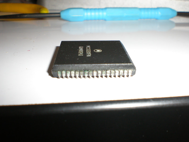
It's working. Unfortunately I had to use the SP3200's FDC as this damned leaked battery damaged the chip apparently...BTW, if someone has a good source for some MCCS3201FN FDC...or maybe I'll wait for the next junk market 
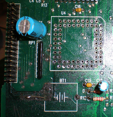
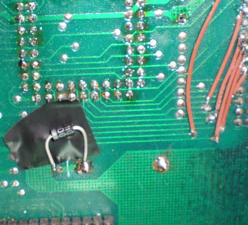
While at it, I added a CR2032 battery socket. Couldn't fit into the holes so I had to bend a pin a solder it on the top of the board.
I cut the trace on the bottom side between + and the resistor and bridged it with the diode.
Works like a charm!
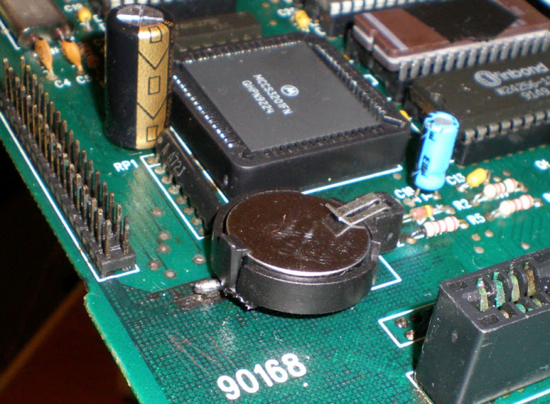
As promised here is a picture of the horrible "make up"...
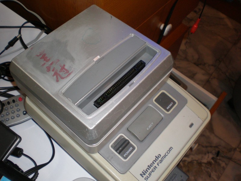
I sanded it a bit to see if it was an authentic Super Pro Fighter and I believe it is...if only I could get rid of that ugly paint.
The Super Pro Fighter is limited to 16M but I might get a special 4M memory cartridge to extend it to 20M, it was especially designed to play to SF2Turbo. I don't believe any other copier ever use a cartridge to extend its memory ... 
|
|
| Back to top |
|
|
amptor
Joined: 14 Nov 2003
Posts: 207
|
| Posted: Thu Jun 11, 2009 9:21 pm Post subject: |
|
|
Damn man that board looks kinda dirty on those photos, might want to hose the entire thing down with some green brakleen, the kind for electronics Or whatever is available at the electronics store.
Also about having wires the proper length. It makes it look neater I guess, but when I began modding PS2 systems I used to make wires and leave the slack in loops and tape it down to the PCB. Some people would hot glue them down, but I thought that might expose the actual wire to the board if it got too hot from the glue.
I still am contemplating cutting the + trace on the battery on my SWC DX and soldering down the CR-2032 battery holder. My battery holder mates exactly to the holes on the PCB and would be a lot cleaner that way. I just have qualms with cutting a trace on what is silently regarded the best SNES backup device ever made.
Well i gotta get back in mine anyway and clean up some flux and if I do any work, I'll need to get a clean tip iron and keep it tinned properly this time. All the irons I have out now are in bad shape. It is a pain to desolder with the generic 30 watt iron I have out now. Probably need to replace the whole iron.
Are you using a Weller or a generic iron? It looks like you didn't have a difficult time desoldering that socket from the board.
Also I'd replace that silicon diode with a germanium one if I was you. Because it looks like you replaced a 3.6V battery with a 3.0V one and that silicon is going to block more voltage going into your BRAM than the germanium one will.
Also why do they expose the window of the BIOS IC on some of these copiers? Is it that there is not enough UV in light to erase it? Both the SWC DX I have at home have stickers covering the window.
_________________
-amptor |
|
| Back to top |
|
|
madman
Joined: 07 Jul 2006
Posts: 598
|
| Posted: Thu Jun 11, 2009 11:34 pm Post subject: |
|
|
| The likelihood of an EPROM that is in some sort of case (like a copier, or a cart, etc) being erased from UV is slim to none. I generally put electrical tape over mine anyhow, but I've opened many of old devices that have EPROMs where the windows aren't covered.
|
|
| Back to top |
|
|
Mystic_Merlin
Joined: 15 Oct 2007
Posts: 533
Location: Bangkok
|
| Posted: Fri Jun 12, 2009 6:27 am Post subject: |
|
|
Ya regarding the EPROM you couldn't erase it with natural light even if u wanted...I just put some tape on it since I was using this piece to hold tight some components while soldering, so it really doesn't matter.
For the iron I'm using a generic 30W iron, quite recent, I also had a 20-40W soldering gun that went bad so I know the pain of heating up some solder for a minute before it melts... I was considering getting a station but for now the 30W does the job just fine although it can get a little too hot for some components. I keep the tip clean and always leave a bit of tin on it to prevent rusting, I hope this one will last longer.
Yesterday I spotted a shop selling pre-tinned wires of different length, how smart is that?
I can understand you don't wanna modify or cut anything on your DX2 but since this SPF was already in a bad shape, one more cut wouldn't hurt
I bought 2 types of battery holder, the one up there and that one:
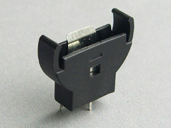
it can give more ideas on how to place these on the copier. I haven't thought yet of any smarter way to install it without modifying the board.
The fist thing I would think of would be wiring the holder to the board and tape it on some free spot on the pcb...
For the diode I'm using a 1N4004, the current is just droping by 0.2V so 2.8V is more than enough to power the SRAM.
|
|
| Back to top |
|
|
CrackLtd
Joined: 05 Feb 2007
Posts: 239
|
| Posted: Fri Jun 12, 2009 7:31 am Post subject: |
|
|
Very helpful tools are a "Hot Air Gun" and a "Iron with combined Vacuum Desoldering" Tool. Both are to get for like $100. See Demonstration:
Vacuum Desoldering: http://www.youtube.com/watch?v=R8nX2yD96AM
Hot Air Gun: http://www.youtube.com/watch?v=AxYhF6Ab2CU
To really make a good job with an copier device in a bad state like you get them from your junk yard i would suggest removing all parts from the main pcb and clean the pcb very carefully so it cannot continue to rust. Then just remount everything back, proper substitute broken parts, changing battery, etc. Just doing a clean job. After that the copier will look like NEW. Thats the way i would do it, if i would do it, hehe.
|
|
| Back to top |
|
|
amptor
Joined: 14 Nov 2003
Posts: 207
|
| Posted: Fri Jun 12, 2009 6:48 pm Post subject: |
|
|
The problem I have heard about the generic soldering irons is that the temperature is not controlled, wheras on the station you are talking about you can supposedly control the temperature. My friend has a weller station that has a digital readout of the temperature.
I robbed the CR-2032 adapter off of a Pentium III motherboard, but they are cheap on ebay like $1 for 50 of them or something. Ridiculous amount of unnecessary items though.
I found a Maxell with 3.0V in it that I guess I'll swap in. I haven't tested the BRAM yet to see if it even holds data with a lower voltage battery.
But yeah I'm going to buy a new iron or at least a new tip before I do anything more. I think 15 watt might put out too low of heat to desolder with so I may just have to buy another iron. But I guess while I'm at it I probably should just get a 30 watt weller and a 12 watt weller, as I can't seem to find a 15 watt weller. 12 should be comperable.
I learned that you need to make sure you keep your tip tinned and before you put it away, you are suppose to tin the tip and then unplug it leaving some solder on it.
Also sometimes it is hard to tell from photos, but your solder joints on the wires look like they might be cold. But I am guessing that they possibly just are oxidized. Although today I look at it and they look a little better, the other points that the factory soldered are pretty oxidized though. It seems like you're suppose to put flux on that solder you already have on the board before you start soldering wires or components to it. However I don't know if ordinary flux has enough acid in it to get rid of that much oxidation and I kinda wonder if there's another product or way to get rid of the oxidation more. These are issues I am having desoldering a USB port from a cel phone right now, I see the oxidation on its solder, my iron's tip is bad, and I can't get good flow at all. The generic 30 watt I'm using might even be burning itself out, the end where the tip goes in is all dark rust color. I probably should just throw the whole iron away and get another one
_________________
-amptor |
|
| Back to top |
|
|
Mystic_Merlin
Joined: 15 Oct 2007
Posts: 533
Location: Bangkok
|
| Posted: Sat Jun 13, 2009 9:40 am Post subject: |
|
|
The Vacuum desoldering thing looks like a handy device! Damn it would have saved me a lot of time
I agree my job on this copier is far from being perfect...
Honestly I believe most ppl must consider nonsense all the time I spent on a first generation Pro Fighter already...
|
|
| Back to top |
|
|
amptor
Joined: 14 Nov 2003
Posts: 207
|
| Posted: Mon Jun 15, 2009 5:13 pm Post subject: |
|
|
Yeah my soldering isn't top notch either but the joint came out ok on my battery. I just need to get a new iron before I go in there and do anything else. I read that the silicon diode causes a lot more voltage drop than the germanium one, so I had some spare germanium diodes from another project and I soldered one of those in line with the CR-2032 holder. I considered seeing if I could get one of those rechargable lithium cell batteries in there instead, but I'm not sure if the wildcard puts out too much electricity to charge it and also I noticed that in the case of the Sega Dreamcast the charge on the battery only lasts a month so I'm not sure if that would still be the case in one of these backup units. I'm guessing that the Dreamcast's battery backup is probably just poorly designed.
_________________
-amptor |
|
| Back to top |
|
|
RealTimeSave
Joined: 03 Oct 2012
Posts: 60
|
| Posted: Sat May 24, 2014 3:56 am Post subject: |
|
|
Wow I just happened across this post yesterday and it was helpful. I took a SWC DX and neutralized the leaked NiCD, clipped the battery off, desoldered a coin cell CR2032 holder from an old PII slot-1 motherboard (that cell holder can take some HEAT! it didn't melt when removing it), took the SWC DX and soldered the coin cell holder onto the opposite side with a spare germanium diode with the anode soldered to the positive terminal of the cell holder and the cathode soldered directly to the board, bent it in a way that the diode does not contact the ground plane of the circuit board, soldered the negative terminal to the (-) (which is marked "+" for some reason on the SWC DX which is incorrect, verified this with a DMM), and put a brand new CR2032 in it which I picked up in a 3 pack at the 99 cent store. No traces have been cut.
I also replaced all the screws with brand new stainless steel ones #4 x 1/2" sheet metal screws pan head phillips 8 pack. Home Depot sells them for $1 and some change after tax. And the two that hold the floppy in I found in a bag of spare computer parts new.
Then I tested the unit and made sure it still works. Now I just have to do this same thing to my other SWC DX which will just take minimal effort.
_________________
-RTS- |
|
| Back to top |
|
|
|