| View previous topic :: View next topic |
| Author |
Message |
Mystic_Merlin
Joined: 15 Oct 2007
Posts: 533
Location: Bangkok
|
 Posted: Mon Jul 20, 2009 11:26 am Post subject: DSP clones & FD clock Posted: Mon Jul 20, 2009 11:26 am Post subject: DSP clones & FD clock |
 |
|
Ok these are 2 different questions but rather than opening 2 threads...
1) I noticed some DSP clones had some of their pin cut or bent off the socket on some copiers.
| Code: | DSP pins
This is how most DSP chips are hooked up.
(DSP is a uPD77C25 made by NEC)
Vcc 01 28 Vcc
Vcc 02 27 register select(A14 used when DSP is mapped to cartridge memory region,
nc 03 26 /CS A12 used when DSP is mapped to expansion memory region)
nc 04 25 /RD
nc 05 24 /WR
D0 06 23 nc
D1 07 22 nc
D2 08 21 Vcc
D3 09 20 Vcc
D4 10 19 Vcc
D5 11 18 Vcc
D6 12 17 GND
D7 13 16 RESET (inverted /RESET- SNES slot)
D8 14 15 CLOCK |
Based on this pinout and providing I'm reading it correctly, these pins would be mostly the CLOCK or the D8 (which does not make sense:roll: ) and some Vcc. Any explanation?
2) On later pro fighters the design of the board has been changed from (1x24Mhz) crystal to (1x16Mhz + 1x7.xxMhz).
I wrote 7.xx coz some of mine have a 7.68Mhz, some a 7.86Mhz, some I can't read...
Well what I understand is that the 24Mhz crystal has to do with the FD clock and data synchronization. I also understand that 16Mhz+7.xx is almost equal to 24Mhz.
Now what could be the reason for such change in design?
What's the value range acceptable for the 7.xx crystal, would 8.00Mhz work? |
|
| Back to top |
|
 |
kyuusaku
Joined: 26 Jul 2003
Posts: 941
Location: .ma.us
|
| Posted: Mon Jul 20, 2009 2:43 pm Post subject: |
|
|
None of those pins cut makes any sense unless they have jumper wires to new signals. Maybe someone tried to disable the internal DSP in a very bad way.
The 24 MHz clock clock was divided by 3 to get 8 MHz for the floppy controller and also served as timing for the DRAM controller. 1/24000000 = 41ns DRAM cycles.
The new board must divide 16 Mhz by 2 for the floppy, and use 62ns DRAM cycles, which sounds worse but must be OK.
You can't add crystal frequencies like that, the 7.xx MHz oscillator could be for DSP if the system clock isn't internally divided by 3 on that chip. You can check by tracing which chip(s) it goes to, depending on the system it drives it might be OK to replace with 8 MHz. |
|
| Back to top |
|
|
Mystic_Merlin
Joined: 15 Oct 2007
Posts: 533
Location: Bangkok
|
| Posted: Mon Jul 20, 2009 5:01 pm Post subject: |
|
|
Thanks kyuusaku!
| kyuusaku wrote: | | You can't add crystal frequencies like that |
Lol, it was too simple...ya sometimes you're lazy and take shortcuts 
| kyuusaku wrote: | | the 7.xx MHz oscillator could be for DSP if the system clock isn't internally divided by 3 on that chip |
Mmm...interesting, actually I just traced one of the pin and it seems to go to the DSP. I got a FX-32 board with no DSP and a missing 7.xx crystal...that could make sense.
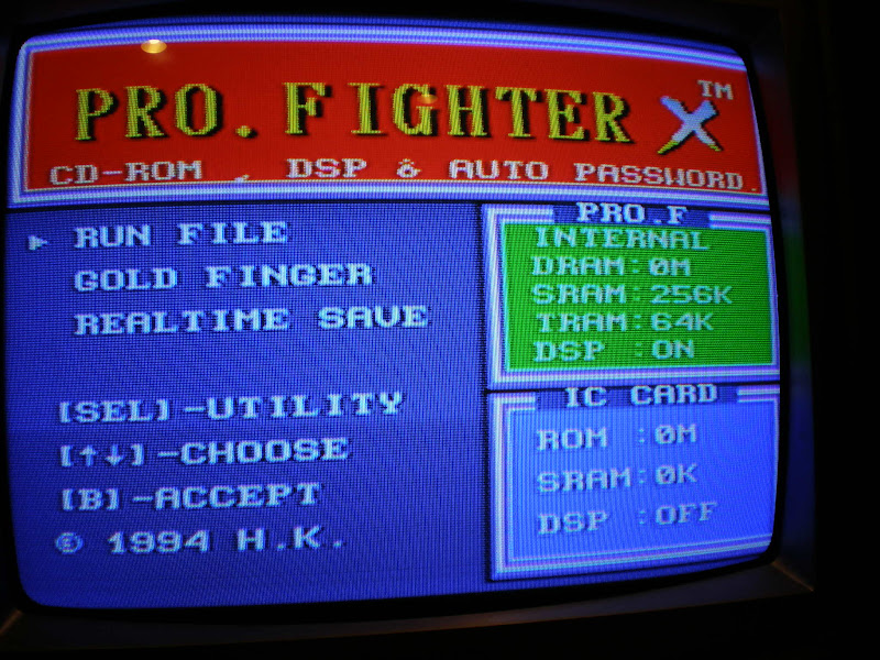
Here are a few pics of my Pro Fighter X 1. Actually I never owned an official PFX so I don't know if this one is?
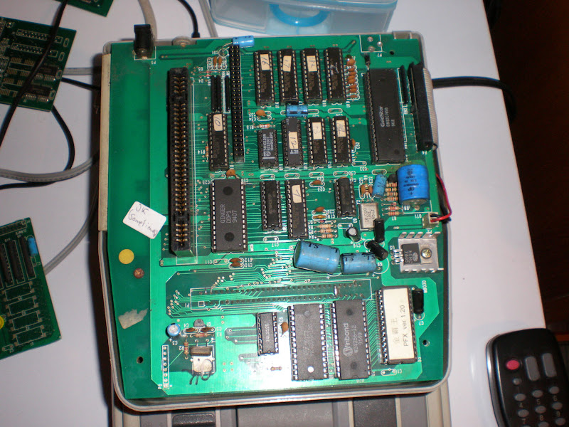
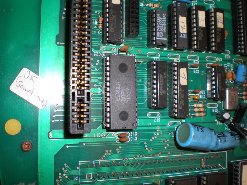
You can see the 2 pins on the DSP are off the socket. I got the exact same mod on 2 other copiers so it's done on purpose. |
|
| Back to top |
|
|
kyuusaku
Joined: 26 Jul 2003
Posts: 941
Location: .ma.us
|
| Posted: Mon Jul 20, 2009 6:05 pm Post subject: |
|
|
I just noticed you have data lines 0-8, that's 9 data lines! There's only an 8-bit bus so I looked up the uPD77C25 datasheet and pin 14 is GND and pin 28 is VCC.
It's slightly possible that the cloned DSP has a different pinout, but I think someone strangely disconnected the power rails, which of course need to be connected for proper operation. Have you tested a DSP game on it? All I can think of is that someone did that so that plugin DSP games wouldn't conflict (I thought Pro Fighters could detect that..), though it's not a real solution at all.
Also looking at the datasheet, DSP operates at ~8 MHz so that crystal most certainly is for DSP. My guess though is that if games didn't need it to run at ~7 MHz, they would have used the 8 MHz floppy clock. To me though it doesn't seem critical since the DSP isn't synchronized to the CPU. |
|
| Back to top |
|
|
Mystic_Merlin
Joined: 15 Oct 2007
Posts: 533
Location: Bangkok
|
| Posted: Mon Jul 20, 2009 6:45 pm Post subject: |
|
|
| kyuusaku wrote: | | I just noticed you have data lines 0-8, that's 9 data lines! There's only an 8-bit bus so I looked up the uPD77C25 datasheet and pin 14 is GND and pin 28 is VCC. |
I got that pinout from a neviksti doc, I guess there's an error on pin 14
| kyuusaku wrote: | | Have you tested a DSP game on it? All I can think of is that someone did that so that plugin DSP games wouldn't conflict (I thought Pro Fighters could detect that..), though it's not a real solution at all. |
I tried Mario Kart, flawless. Now I don't have a DSP cart to test but maybe someone with an original PFX could tell if it does cause some issue. |
|
| Back to top |
|
|
|

